1. Any man who successfully convinces a monkey that honey is sweeter than banana, is capable of selling condoms to a Roman father.
2. Dear ladies, If your boyfriend didn’t wish you a happy mother’s
day or sing sweet mother for you, you should stop breastfeeding him.
3. He who swallows a complete coconut have absolute trust in his anus.
4. Dear sisters, don’t be deceived by a man who text you “I miss you” only when it’s raining, because you are not an umbrella.
5. Swimming pool is more useful than Liverpool.
6. If over 15 guys have sucked your breasts, you don’t need to call
those things “your breasts”, It’s called COW BELL, OUR MILK! – Repeat
after me, OUR MILK!
7. It’s hard to bewitch African girls these days. Every time you take
a piece from her hair to the witch doctor, either a Brazilian innocent
woman gets mad or a factory in China catches fire.
8. All I hear always is, ‘No sex before marriage?’ If that was God’s
plan, then you would receive your penis or vagina on your wedding day.
9. The only warning Africans take serious is LOW BATTERY.
10. Men sucking lady’s breast is normal because the act was learnt in
childhood when they were young but the act of lady’s sucking men’s d*ck
is what baffles me, where did they learn it from?
11. Whenever things seem to start going well in your life, the Devil comes along and gives you a ‘girlfriend’.
12. When your clothes are made of cassava leaves, you don’t take a goat as a friend.
13. If you have attended over 100 weddings in your life and still single, you are not different from a Canopy.
14. Dating a slim/slender guy is cool. The problem is when you are
lying on his chest then his ribs draw adidas lines on your face.
15. If you are ugly, you are ugly. Stop talking about inner beauty
because men don’t walk around with X-rays to see inner beauty.
16. Respect pregnant women because it’s not easy walking around with evidence that you’ve had sex.
17. Some of the girls of today can’t even jog for 5 minutes but they
expect a guy to last in bed with you for 2 hours? Your level of
selfishness demands a one week crusade.
18. I stopped trusting ladies when my class 3 girlfriend left me for another boy all because he bought a sharpener wid a mirror.
19. Nothing makes a woman more confused than being in a relationship with a “broke” man who’s extremely good in bed.
20. Witchcraft is when a 24 year old girl who cannot jog for 5 minutes expects a 40 year old man to last for 1 hour in bed.
21. Being dumped by a dark-skinned girl is the worst thing ever;
because anytime you get home and see charcoal, you become emotional.
22. Women with beauty and no brains, it is your private parts will suffer the most.
23. When one’s goat gets missing, the aroma of a neighbour’s soup gets suspicious.
24. Its better for a man to be stingy with his money because he hustled for it than a woman to deny you a hole she didn’t drill.
25. Even Satan wasn’t gay, he approached naked Eve instead of naked Adam. Say no to same-sex marriage.
26. If you are a married man and you find yourself attracted to school girls, just buy your wife a school uniform.
27. It is every man’s dream to remove a woman’s pant one day but NOT when it’s on a drying line.
28. Virginity is the best wedding gift any man would receive from his
newly wed wife but lately, there’s nothing as such any-longer because
it’ll have already been given out as a Birthday gift, token of
Appreciation, Job assurance, Church collection, Examination marking
schemes & for Lorry fares!”
29. Treat every part of your towel nicely because the part that wipes your buttocks today will wipe your face tomorrow.
30. We are living in a generation where people “in love” are free to
touch each others’ private parts but cannot touch each others’ phones
because they’re private.”
31. Sometimes you look back at girls you spent money on rather than send it to your mum and you realise witchcraft is real.
32. If President Barack Obama wants me to allow marriage for same-sex
couples in my country (Zimbabwe), he must come here so that I marry him
first.
33. South Africans will kick down a statue of a dead white man but
won’t even attempt to slap a live one. Yet they can stone to death a
black man simply because he’s a foreigner.
34. What is the problem? We now have aeroplanes which can take them back quicker than the ships used by their ancestors.
35. Mr Bush, Mr. Blair and now Mr Brown’s sense of human rights
precludes our people’s right to their God-given resources, which in
their view must be controlled by their kith and kin. I am termed
dictator because I have rejected this supremacist view and frustrated
the neo-colonialists.
36. Cigarette is a pinch of tobacco rolled in a piece of paper with fire on one end and a fool on the other end.
37. A brave man is he who has a running stomach and still wants to flatulate.
38. Journalist: Sir don’t you think 89 years would be a great time to retire as a President.
Mugabe: Have you ever asked the Queen this question or is it just for African leaders?
39. Interviewer: Mr President, when are you bidding the people of Zimbabwe farewell?
Robert: Where are they going?
40. My dear ladies, please don’t buy a selfie stick when your armpit itself needs a shaving stick.
Friday, September 23, 2016
Arduino projects
Blink
This example shows the simplest thing you can do with an Arduino or Genuino to see physical output: it blinks an LED.Hardware Required
- Arduino or Genuino Board
- LED
- 220 ohm resistor
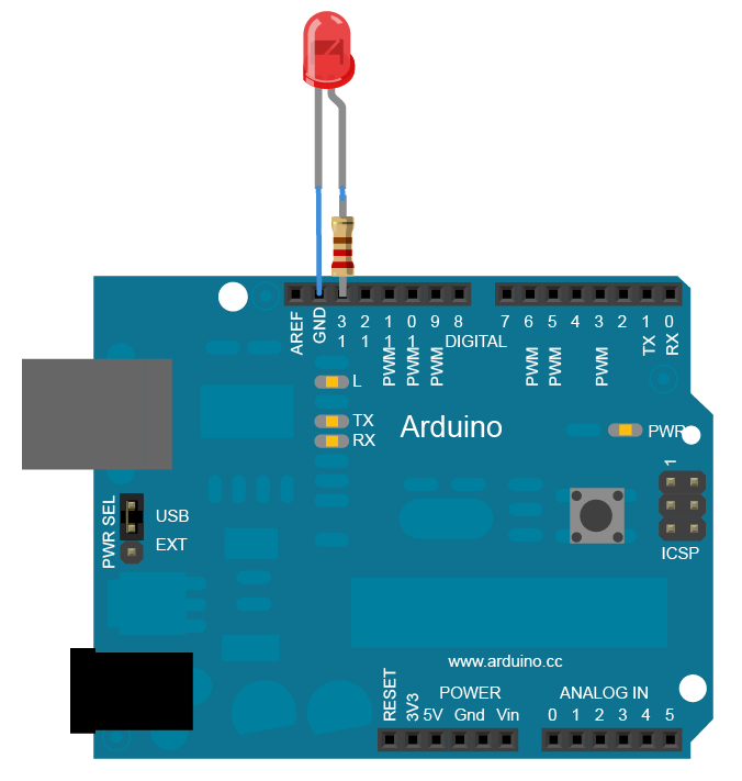
Circuit
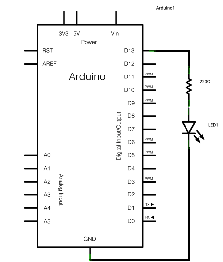
To build the circuit, connect one end of the resistor to Arduino pin 13. Connect the long leg of the LED (the positive leg, called the anode) to the other end of the resistor. Connect the short leg of the LED (the negative leg, called the cathode) to the Arduino GND, as shown in the diagram and the schematic below.Most Arduino boards already have an LED attached to pin 13 on the board itself. If you run this example with no hardware attached, you should see that LED blink.
The value of the resistor in series with the LED may be of a different value than 220 ohm; the LED will lit up also with values up to 1K ohm.
Schematic
Code
After you build the circuit plug your Arduino or Genuino board into your computer, start the Arduino Software (IDE) and enter the code below. You may also load it from the menu File/Examples/01.Basics/Blink . The first thing you do is to initialize pin 13 as an output pin with the linepinMode(13, OUTPUT);In the main loop, you turn the LED on with the line:
digitalWrite(13, HIGH);This supplies 5 volts to pin 13. That creates a voltage difference across the pins of the LED, and lights it up. Then you turn it off with the line:
digitalWrite(13, LOW);That takes pin 13 back to 0 volts, and turns the LED off. In between the on and the off, you want enough time for a person to see the change, so the
delay() commands tell the board to do nothing for 1000 milliseconds, or one second. When you use the delay() command, nothing else happens for that amount of time. Once you’ve understood the basic examples, check out the BlinkWithoutDelay example to learn how to create a delay while doing other things.Once you’ve understood this example, check out the DigitalReadSerial example to learn how read a switch connected to the board.
/*
Blink
Turns on an LED on for one second, then off for one second, repeatedly. Most Arduinos have an on-board LED you can control. On the UNO, MEGA and ZERO
it is attached to digital pin 13, on MKR1000 on pin 6. LED_BUILTIN takes care
of use the correct LED pin whatever is the board used.
If you want to know what pin the on-board LED is connected to on your Arduino model, check
the Technical Specs of your board at https://www.arduino.cc/en/Main/Products
This example code is in the public domain.
modified 8 May 2014
by Scott Fitzgerald
modified 2 Sep 2016
by Arturo Guadalupi
*/
// the setup function runs once when you press reset or power the board
void setup() {
// initialize digital pin LED_BUILTIN as an output.
pinMode(LED_BUILTIN, OUTPUT);
}
// the loop function runs over and over again forever
void loop() {
digitalWrite(LED_BUILTIN, HIGH); // turn the LED on (HIGH is the voltage level)
delay(1000); // wait for a second
digitalWrite(LED_BUILTIN, LOW); // turn the LED off by making the voltage LOW
delay(1000); // wait for a second
}
- setup()
- loop()
- pinMode()
- digitalWrite()
- delay()
- AnalogReadSerial – Read a potentiometer, print its state out to the Arduino Serial Monitor.
- BareMinimum – The bare minimum of code needed to start an Arduino sketch.
- DigitalReadSerial – Read a switch, print the state out to the Arduino Serial Monitor.
- Fade – Demonstrates the use of analog output to fade an LED.
- ReadAnalogVoltage – Reads an analog input and prints the voltage to the serial monitor.
Blink Without Delay
Sometimes you need to do two things at once. For example you might want to blink an LED while reading a button press. In this case, you can’t usedelay(), because Arduino pauses your program during the delay(). If the button is pressed while Arduino is paused waiting for the delay() to pass, your program will miss the button press.This sketch demonstrates how to blink an LED without using
delay(). It turns on the LED on and then makes note of the time. Then, each time through loop(),
it checks to see if the desired blink time has passed. If it has, it
toggles the LED on or off and makes note of the new time. In this way
the LED blinks continuously while the sketch execution never lags on a
single instruction.An analogy would be warming up a pizza in your microwave, and also waiting some important email. You put the pizza in the microwave and set it for 10 minutes. The analogy to using
delay() would be
to sit in front of the microwave watching the timer count down from 10
minutes until the timer reaches zero. If the important email arrives
during this time you will miss it.What you would do in real life would be to turn on the pizza, and then check your email, and then maybe do something else (that doesn’t take too long!) and every so often you will come back to the microwave to see if the timer has reached zero, indicating that your pizza is done.
In this tutorial you will learn how to set up a similar timer.
Hardware Required
- Arduino or Genuino Board
- LED
- 220 ohm resistor
Circuit
Most Arduino and Genuino boards already have an LED attached to pin 13 on the board itself. If you run this example with no hardware attached, you should see that LED blink.
Schematic
click the image to enlargeCode
The code below uses themillis()
function, a command that returns the number of milliseconds since the
board started running its current sketch, to blink an LED.
/* Blink without Delay
Turns on and off a light emitting diode (LED) connected to a digital
pin, without using the delay() function. This means that other code
can run at the same time without being interrupted by the LED code.
The circuit:
* LED attached from pin 13 to ground.
* Note: on most Arduinos, there is already an LED on the board
that’s attached to pin 13, so no hardware is needed for this example.
created 2005
by David A. Mellis
modified 8 Feb 2010
by Paul Stoffregen
modified 11 Nov 2013
by Scott Fitzgerald
This example code is in the public domain.
http://www.arduino.cc/en/Tutorial/BlinkWithoutDelay
*/
// constants won’t change. Used here to set a pin number :
const int ledPin = 13; // the number of the LED pin
// Variables will change :
int ledState = LOW; // ledState used to set the LED
// Generally, you should use “unsigned long” for variables that hold time
// The value will quickly become too large for an int to store
unsigned long previousMillis = 0; // will store last time LED was updated
// constants won’t change :
const long interval = 1000; // interval at which to blink (milliseconds)
void setup() {
// set the digital pin as output:
pinMode(ledPin, OUTPUT);
}
void loop() {
// here is where you’d put code that needs to be running all the time.
// check to see if it’s time to blink the LED; that is, if the
// difference between the current time and last time you blinked
// the LED is bigger than the interval at which you want to
// blink the LED.
unsigned long currentMillis = millis();
if (currentMillis – previousMillis >= interval) {
// save the last time you blinked the LED
previousMillis = currentMillis;
// if the LED is off turn it on and vice-versa:
if (ledState == LOW) {
ledState = HIGH;
} else {
ledState = LOW;
}
// set the LED with the ledState of the variable:
digitalWrite(ledPin, ledState);
}
}
SIREN CHEAP AND EASY
 In this project, two 555 timer IC's were used the first one is operating in
Astable mode ( ie output is switching between high and low without any
intervention from the user ) and is used to designed such that to
produce a low frequency. Well the second one also operating in
Astable mode but it is driven by the output of the first timer by using
the control voltage pin 5 .Due to this up and down in the control
voltage it produces a wailing sound. The Police Siren circuit uses two 555's to produce an up-down wailing
sound. The first 555 is wired as a low-frequency oscillator to
control the VOLTAGE CONTROL pin 5 of the second 555. The
voltage shift on pin 5 causes the frequency of the second oscillator
to rise and fall.
In this project, two 555 timer IC's were used the first one is operating in
Astable mode ( ie output is switching between high and low without any
intervention from the user ) and is used to designed such that to
produce a low frequency. Well the second one also operating in
Astable mode but it is driven by the output of the first timer by using
the control voltage pin 5 .Due to this up and down in the control
voltage it produces a wailing sound. The Police Siren circuit uses two 555's to produce an up-down wailing
sound. The first 555 is wired as a low-frequency oscillator to
control the VOLTAGE CONTROL pin 5 of the second 555. The
voltage shift on pin 5 causes the frequency of the second oscillator
to rise and fall.
You can also apply it for some different sound like Ambulance , Police Car , Alert Alarm etc by changing the frequency of the first timer all you have to do is to change different resistance by using the potentiometer and try some different valued electrolytic capacitors .
LIST OF COMPONENTS
1. NE555 timer ic (2)
2. 10uF electrolytic capacitor (2)
3. 100nF Ceramic capacitor (2)
4. 10k resistor (3)
5. 1k resistor (1)
6. 68k resistor (1)
7. Speaker 0.5 watt OR any (1)
8. 9v battery and clip (1)
9. One small breadboard (1)
10. Some jumper wires.


CIRCUIT DIAGRAM


Wednesday, September 21, 2016
555 Timer Flashing Led
This circuit uses the 555 timer IC in an astable operating mode which
generates a continuous output via Pin 3 in the form of a square wave.
This turns the LED (D1) on and off. The speed at which the LED (D1) is
turned on and off is set by the values of R1 and R2.
 PART LIST
R1: 1K
R2: 470K
R3: 1K
D1: LED
C1: 1 uF
and 555 Timer
Basics
The final outcome of this project is to build a circuit which results with an LED that blinks on and off. This project is centered around the 555 timer chip, a short description of how the 555 timer chip works will be helpful.
The 555 Timer
The 555 timer is an integrated circuit (a circuit built on a piece of semi conductor material that performs a defined function) which can be used in many applications which require oscillator, pulse generation, or timer controlled devices. The 555 timer has 3 operating modes; monostable, astable, and bistable. This utilizes the 555 in astable mode, thus we will focus on the basics of astable operation.
Astable operation - in astable mode, the 555 outputs a constant stream of rectangular pulses. The rectangular pulses will be outputted at a specific frequency that is defined by the components that are placed in between the pins of the 555 timer. Lets start by looking at the Pin connections and functions of the 555 IC.
PINS
Pin 1 (GROUND) - The ground (or common) pin is the most-negative supply potential of the device, which is normally connected to circuit common when operated from positive supply voltages.
Pin 2 (Trigger) - This pin is the input which causes the output to go high and begin the timing cycle. Triggering occurs when the trigger input moves from a voltage above 2/3 of the supply voltage to a voltage below 1/3 of the supply. For example using a 12 volt supply, the trigger input voltage must start from above 8 volts and move down to a voltage below 4 volts to begin the timing cycle. The action is level sensitive and the trigger voltage may move very slowly. To avoid retriggering, the trigger voltage must return to a voltage above 1/3 of the supply before the end of the timing cycle in the monostable mode. Trigger input current is about 0.5 microamps.
Pin 3 (Output) - The output pin of the 555 moves to a high level of 1.7 volts less than the supply voltage when the timing cycle begins. The output returns to a low level near 0 at the end of the cycle. Maximum current from the output at either low or high levels is approximately 200 mA.
Pin 4 (Reset) - A low logic level on this pin resets the timer and returns the ouput to a low state. It is normally connected to the + supply line if not used.
Pin 5 (Control) - This pin allows changing the triggering and threshold voltages by applying an external voltage. When the timer is operating in the astable or oscillating mode, this input could be used to alter or frequency modulate the output. If not in use, it is recommended installing a small capacitor from pin 5 to ground to avoid possible false or erratic triggering from noise effects.
Pin 6 (Threshold) - Pin 6 is used to reset the latch and cause the output to go low. Reset occurs when the voltage on this pin moves from a voltage below 1/3 of the supply to a voltage above 2/3 of the supply. The action is level sensitive and can move slowly similar to the trigger voltage.
Pin 7 (Discharge) - This pin is an open collector output which is in phase with the main output on pin 3 and has similar current sinking capability.
Pin 8 (V +) - This is the positive supply voltage terminal of the 555 timer IC. Supply-voltage operating range is +4.5 volts (minimum) to +16 volts (maximum).
CIRCUIT DIAGRAM


20W AMPLIFIER SIMPLE CIRCUIT
Audio Power Amplifier with TDA2003
TDA2003 is a cheap amplifier that is designed to run on single rail power supplies (unipolar). It provides a high output current capability (up to 3.5A), very low harmonic and cross-over distortion. TDA2003 has improved performance with the same pin configuration
as the TDA 2002. The features of TDA 2002 - very low number of external
components, ease of assembly, space and cost saving - are maintained.
TDA2003 has improved performance with the same pin configuration
as the TDA 2002. The features of TDA 2002 - very low number of external
components, ease of assembly, space and cost saving - are maintained.
The device provides a high output current capability (max. 3.5A), very low harmonic and cross-over distortion. A completely safe operation is guaranteed due to protection against DC and AC short circuit between all pins and ground, thermal over-range, load dump voltage surge up to 40V and fortuitous open ground.

ABSOLUTE MAXIMUM RATINGS:
VS - Peak supply voltage (50ms): 40 V
VS - Operating supply voltage: 18 V
IO - Output peak current (repetitive): 3.5 A
Ptot - Power dissipation at Tcase = 90°C: 20 W
Tstg,Tj - Storage and junction temp.: -40 to 150°C
CIRCUIT DIAGRAM

Monday, September 19, 2016
555 timer IC usage

The 555 timer IC is an integrated circuit (chip) used in a variety of timer, pulse generation, and oscillator applications. The 555 can be used to provide time delays, as an oscillator, and as a flip-flop element. Derivatives provide up to four timing circuits in one package.
 The NE555 parts were commercial temperature range, 0 °C to +70 °C, and the SE555
part number designated the military temperature range, −55 °C to +125
°C. These were available in both high-reliability metal can (T package)
and inexpensive epoxy plastic (V package) packages. Thus the full part
numbers were NE555V, NE555T, SE555V, and SE555T. It has been
hypothesized that the 555 got its name from the three 5 kΩ resistors used within, but Hans Camenzind has stated that the number was arbitrary.
The NE555 parts were commercial temperature range, 0 °C to +70 °C, and the SE555
part number designated the military temperature range, −55 °C to +125
°C. These were available in both high-reliability metal can (T package)
and inexpensive epoxy plastic (V package) packages. Thus the full part
numbers were NE555V, NE555T, SE555V, and SE555T. It has been
hypothesized that the 555 got its name from the three 5 kΩ resistors used within, but Hans Camenzind has stated that the number was arbitrary. Low-power versions of the 555 are also available, such as the 7555 and CMOS TLC555. The 7555 is designed to cause less supply noise than the classic 555
and the manufacturer claims that it usually does not require a "control"
capacitor and in many cases does not require a decoupling capacitor
on the power supply. Those parts should generally be included, however,
because noise produced by the timer or variation in power supply
voltage might interfere with other parts of a circuit or influence its
threshold voltages.
Low-power versions of the 555 are also available, such as the 7555 and CMOS TLC555. The 7555 is designed to cause less supply noise than the classic 555
and the manufacturer claims that it usually does not require a "control"
capacitor and in many cases does not require a decoupling capacitor
on the power supply. Those parts should generally be included, however,
because noise produced by the timer or variation in power supply
voltage might interfere with other parts of a circuit or influence its
threshold voltages.Modes
The IC 555 has three operating modes:- Bistable mode or Schmitt trigger – the 555 can operate as a flip-flop, if the DIS pin is not connected and no capacitor is used. Uses include bounce-free latched switches.
- Monostable mode – in this mode, the 555 functions as a "one-shot" pulse generator. Applications include timers, missing pulse detection, bounce-free switches, touch switches, frequency divider, capacitance measurement, pulse-width modulation (PWM) and so on.
- Astable (free-running) mode – the 555 can operate as an electronic oscillator. Uses include LED and lamp flashers, pulse generation, logic clocks, tone generation, security alarms, pulse position modulation and so on. The 555 can be used as a simple ADC, converting an analog value to a pulse length (e.g., selecting a thermistor as timing resistor allows the use of the 555 in a temperature sensor and the period of the output pulse is determined by the temperature). The use of a microprocessor-based circuit can then convert the pulse period to temperature, linearize it and even provide calibration means.
Bistable

Schematic of a 555 in bistable mode
Monostable
See also: RC circuit

Schematic of a 555 in monostable mode

The output pulse width of time t, which is the time it takes to charge C to 2/3 of the supply voltage, is given by
Pins
Pinout diagram
| Pin | Name | Purpose |
|---|---|---|
| 1 | GND | Ground reference voltage, low level (0 V) |
| 2 | TRIG | The OUT pin goes high and a timing interval starts when this input falls below 1/2 of CTRL voltage (which is typically 1/3 VCC, CTRL being 2/3 VCC by default if CTRL is left open). More simply we can say that OUT will be high as long as the trigger is kept at low voltage. Output of the timer totally depends upon the amplitude of the external trigger voltage applied to this pin. |
| 3 | OUT | This output is driven to approximately 1.7 V below +VCC, or to GND. |
| 4 | RESET | A timing interval may be reset by driving this input to GND, but the timing does not begin again until RESET rises above approximately 0.7 volts. Overrides TRIG which overrides THR. |
| 5 | CTRL | Provides "control" access to the internal voltage divider (by default, 2/3 VCC). |
| 6 | THR | The timing (OUT high) interval ends when the voltage at THR ("threshold") is greater than that at CTRL (2/3 VCC if CTRL is open). |
| 7 | DIS | Open collector output which may discharge a capacitor between intervals. In phase with output. |
| 8 | VCC | Positive supply voltage, which is usually between 3 and 15 V depending on the variation. |
Saturday, October 2, 2010
Love sms
It was a day
When I saw no chance
Of being happy
but when you came
Into my life
My heart is shining again.I saw something in a store display today, it was so beautiful, wonderful and adorable. I was close to buying it 4 u, but then I realized it was my own reflection.
When I saw no chance
Of being happy
but when you came
Into my life
My heart is shining again.I saw something in a store display today, it was so beautiful, wonderful and adorable. I was close to buying it 4 u, but then I realized it was my own reflection.
Subscribe to:
Posts (Atom)